Previous article
Fiber Optic Transceivers for 5G Networking Equipment
Octopart Staff
Despite the efficiency and high torque of brushless DC motors, large brushed motors and servos are still very common in many industrial applications. This is mainly because brushed motors are simpler to control, and typically cheaper to buy, and therefore the need to drive them isn’t going anywhere. A small brushed motor-driver integrated circuit won’t cut it for larger industrial motors or servos requiring high voltage, amerperage, or both. This makes it necessary to build the H-bridge from discrete components. This should not be considered a daunting task, as it is not a very complicated schematic; it boils down to 4 FETs with protection diodes, a set of gate drivers, and a controller IC that makes sure you don’t short circuit anything. The gate drivers and controller IC can even be found in a single package if you so desire.
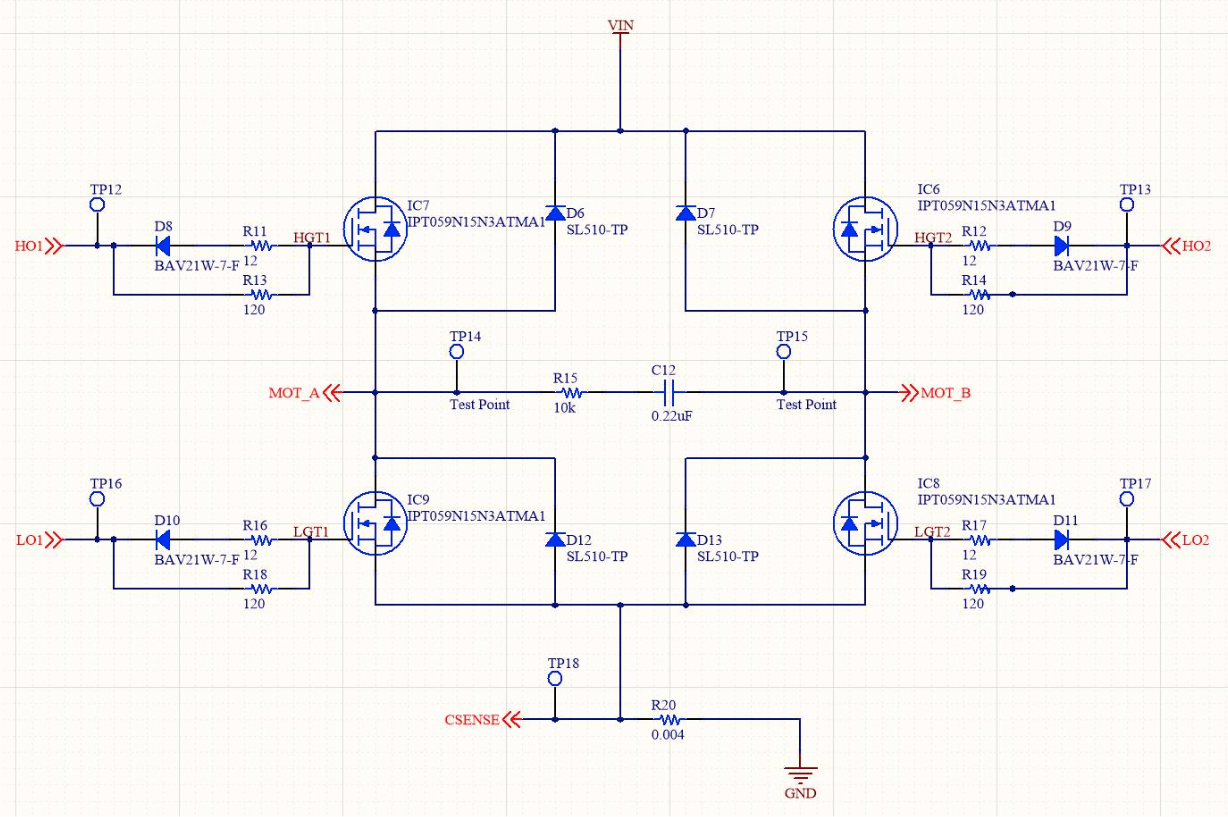
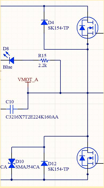
This is a typical H-bridge design, without the gate drivers. You have two options for building the bridge, either to use P-channel MOSFETs for the high side and N-channel for the low side, or to use N-channel all around. As I’m sure you’re aware, P-channel MOSFETS have significantly higher RDS(on) (Internal Resistance) than N-channel ones, which generates a lot more heat from power dissipated in the resistance when conducting high currents. However, P-channel FETs are very convenient to use for the high side, as an N-channel FET will only conduct when the gate has a higher voltage than the source applied. This is where gate drivers come in, as they are able to drive the gate of an N-channel FET by boosting the input voltage sufficiently, which reduces cost and the thermal load on the circuit board.
Another advantage of the gate driver is the ability to both move a lot more current into the MOSFETs’ gate and rapidly drain charge out of it than a typical microcontroller pin could. If you are simply using the H-bridge to turn the motor on in either direction, this won’t be of much advantage to you. However, if you are using high frequency PWM to vary the motor’s speed, or to build a servo, this ability to drive large amounts of current to and from the gate of the FETs can allow you to build a very high performance solution.
Due to the huge advantage of N-channel FETs when it comes to internal resistance and gate capacitance, we are going to focus exclusively on building an H-bridge with N-channel on both the high and low sides.
If you are working with high voltages, high PWM speeds, or both, you might want to look at using two individual drivers for the H-Bridge. While single MOSFET gate drivers are great, high voltage and current will exceed the operational limits of a single IC due to packaging constraints. You might be running high PWM frequencies for the drivers if you’re building a DC servo controller, and need to make many small adjustments to the motor position. Such frequencies require charging and discharging the gate charge on the MOSFET rapidly, which in turn requires significant current.
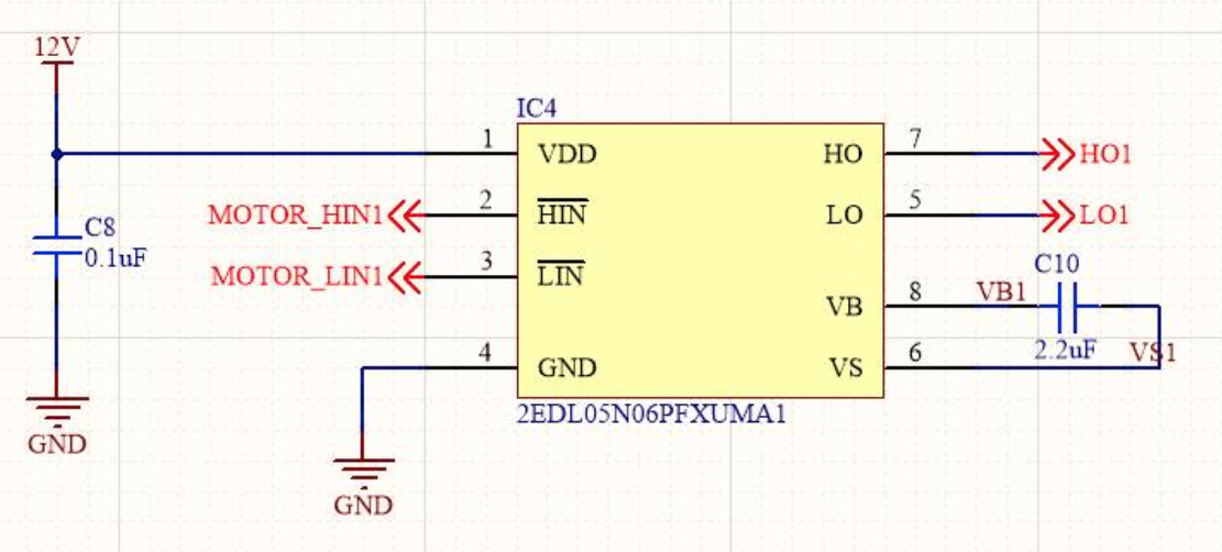
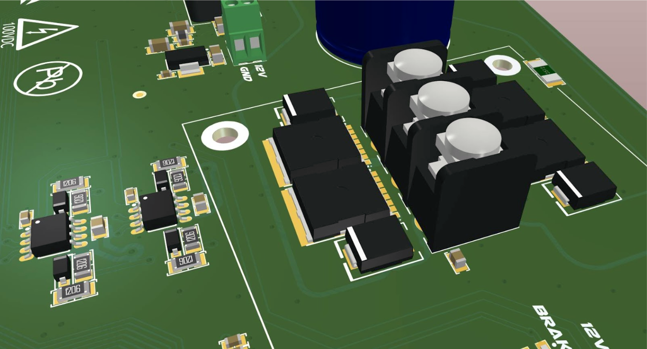
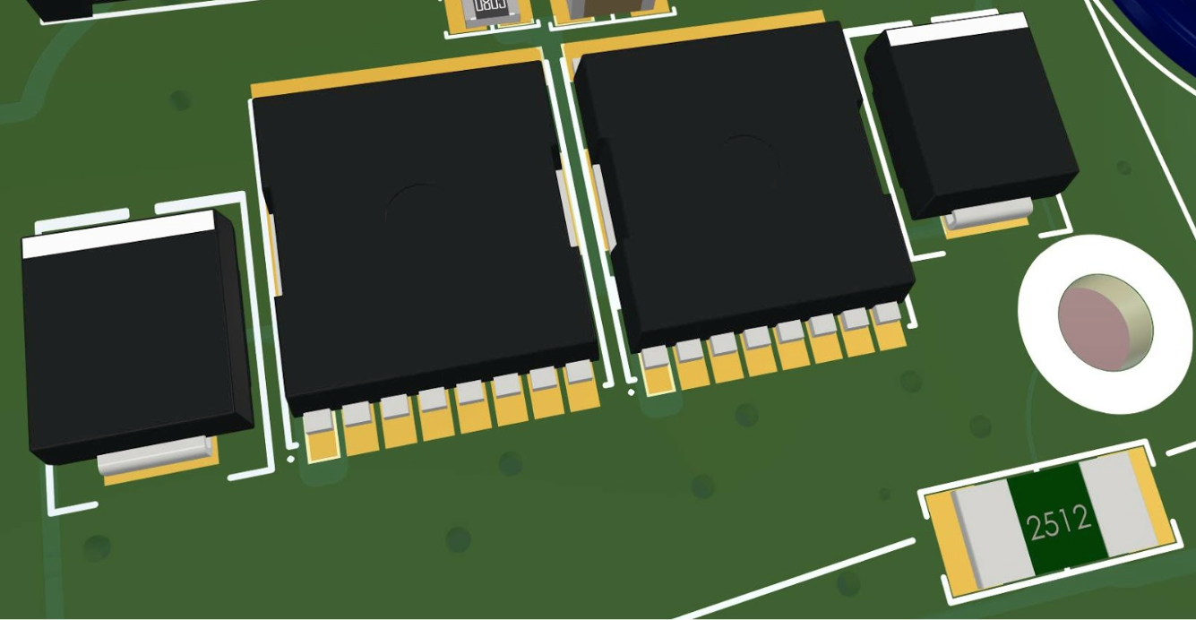
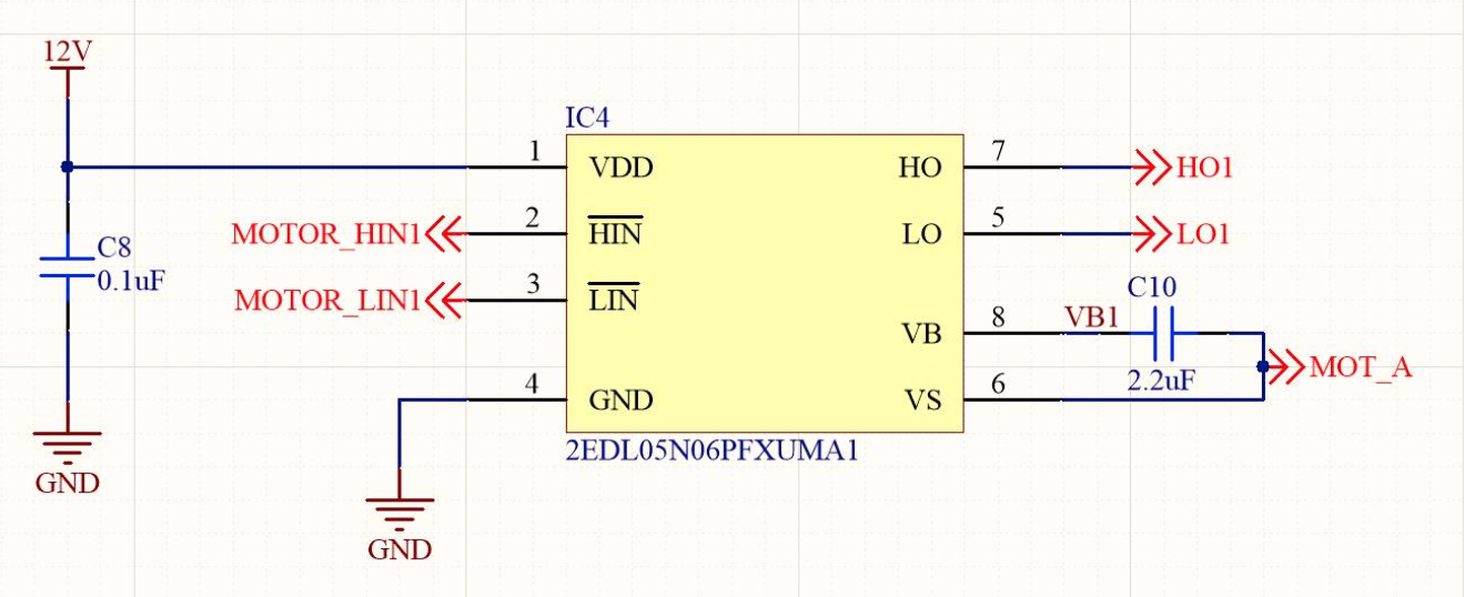
In this schematic, I use two Infineon 2EDL05N06PFXUMA1 from the EiceDriver gate driver range. The truth table signals need to be well managed by the microcontroller to ensure you don’t have a shoot-through condition that will instantly fry the H-Bridge. The tradeoff for this lack of protection against bad programming compared to an integrated full bridge driver package is up to 600V drive capability and significant source/sink current for switching the gate rapidly.
The schematic screenshots above are from my heavy duty servo repository on GitHub. This open source project is based on the open source work of Citrus CNC in their Tarocco DC servo drives. This 100V DC servo driver was used to control the motors in a Siemens SiPlace conversion project.
If you are working with lower voltages, using an integrated circuit to handle both sides of the H-Bridge becomes feasible and can offer some space savings as well as peace of mind with integrated shoot-through protection. When I need a single driver, I typically turn to the Renesas HIP4081A, which comes from a long heritage of industrial quality controllers in the same series.
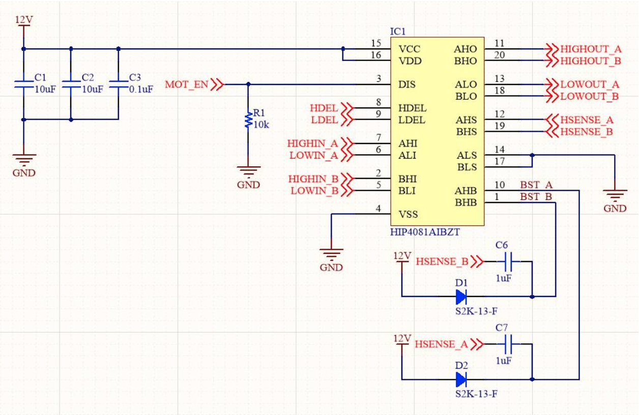
The HIP4081A and most other drivers are very simple to implement, with just a couple of passives required for decoupling and bootstrapping for the high side gate voltages. The schematic above is from a 12V, 100A motor controller that was used in the oil and gas industry.
Whether you use single, dual, or quad gate drivers for your H-Bridge, the basic specifications to consider will be the same. Your primary concerns will likely go towards the MOSFETs used in the bridge, as well as the protection diodes that go with them. Once you have selected each part however, you will need to go back through your other selected parts to ensure the system is optimal. The critical points here are the Gate to Source Voltage on the MOSFET versus the FET driver output voltage, and the protection diode clamping voltage versus the MOSFET maximum drain-source voltage. If you are running high frequency PWM for the H-Bridge, you will also need to consider the FET driver current versus the MOSFET’s gate charge/input capacitance. We will, however, go through the specifications of each part in our H-bridge in great detail to serve as a guide for your part selection process.
There are a couple of relevant temperature listings you might see in a datasheet that cause some of these specifications to be derated, which can be confusing if not dealt with regularly. You will typically see TA, TC and TJ listed:
TA is the device without any cooling other than the PCB at ambient temperature, which is typically listed as 25°C.
TC is the case temperature, which assumes the case is being forcibly cooled to this temperature by a large heatsink and forced air or liquid cooling.
TJ is the temperature of the gate junction, the silicon within the package. It’s not possible to measure this without decapping the IC, so you will need to use the thermal characteristics of the device to calculate this.
If you are not using a large heatsink and active (forced air or liquid) cooling you should base your selections on the TA ratings to create a shortlist, then break out the calculator and actually calculate which device will work best for your specific circuit. MOSFETs can continue working well beyond what you might feel is reasonable for other devices on the circuit board. They function within their specified parameters with junction temperatures reaching or exceeding 175°C, which does give you a lot of leeway for the MOSFET. However, other components on the circuit board nearby may not be so pleased with such high temperatures for extended durations. Below are some of the most important parameters of a MOSFET and how they affect your controller.
The MOSFET’s voltage should be pretty obvious, but if you get too focused on optimising other specifications, you might accidentally select a part that is a little too low voltage than you need. The voltage needs to be, at a bare minimum, the supply voltage to the motor, but realistically should be at least 25% higher, as you will see a large spike when braking the motor while it is moving quickly. As such, this is a good specification to come back and recheck once you have selected your protection diodes. Ensure that Vdss is higher than the camping voltage of the diodes or your MOSFET will burn out rapidly.
Some MOSFET drivers will generate higher voltages than others; while this is not usually an issue, it’s worth bearing in mind. For example, if your driver is generating a voltage that is 10V higher than the source voltage, but the MOSFET is only able to survive 8V, it might not last very long. Likewise, some MOSFETs might require a higher drive voltage to reach the minimum RDS(on), and your driver may not provide that voltage. VGS and RDS(on) at VGS of the MOSFET therefore should be evaluated when looking at the MOSFET driver IC to ensure an optimal system.
The FET resistance is one critical specification as it is directly related to the amount of energy lost as heat in the integrated circuit. If the package can’t remove heat fast enough, the integrated circuit may enter a self-protection mode, or release its magic smoke. With lower RDS(on), you can also have a smaller heatsink or copper area around the IC. Regardless of the rated current of the device, heat is the true limiter. If you have a limited area around the driver for copper pour to act as a heatsink, you will need to prioritize the RDS(on) specification so the driver generates as little heat as possible.
Unless you are only pulsing the motor irregularly, or have a very large heatsink, the drain current is probably one of the least critical specifications for comparing MOSFETs. Like Vdss, you need to make sure your chosen device has a sufficiently high ID to allow your motor to operate, including startup and stall current. ID will likely not be a limiting factor for the device, since being able to remove sufficient heat from the junction/package is likely to be the true limit to how much current you can pass through the device. Some manufacturers such as Infineon will list the ID in their datasheets for various conditions (VGS voltage, copper area, etc) to give you an idea of de-rating. The IPT004N03LATMA1 datasheet for example shows the device capable of 300A under most conditions. However, with just 6cm2 of copper area it is only capable of 72A.
Typically, you will find Ptot to be significantly more limiting than ID. If we look at another MOSFET in a remarkably small package with a much higher RDS(on) than the rather incredible Infineon MOSFET above, such as the Nexperia PMZB290UNE, we can see how the maximum total power dissipation limits usage. This device has a RDS(on) of 380 milliohm, a maximum current of 1 amp and maximum voltage of 20 volts. With 1cm2 of copper area, and a 25°C ambient temperature, the maximum power dissipation of this device is rated to 360mW. We can notice that this rating is reached with only 290mA and 3.3V, which is far less than the voltage or current ratings of the device. We can conclude that the device supports up to 20V, or up to 1A, but not both at the same time due to total power dissipation constraints.
Early in the article, I mentioned how the ability for a driver to move a lot of current into a MOSFET’s gate is important. Gate charge, which is responsible for gate capacitance, is most of the reason behind that. Every time you switch the gate on, you need to supply this much energy, or the gate will not switch on. The faster you can supply the charge, the faster you can switch the gate. The faster and more frequently you switch the gate, the higher your gate current will be. These charges are quite small, but if you switch the gate on a million times a second, the current required to charge and discharge the gate adds up significantly. You can read in great detail about how gate charge affects switching time in an in depth application note from Vishay. Generally though, when looking at a driver, you need to consider how much current it will need to supply by calculating the amount of charge your MOSFET needs at the frequency your system will run.
Very closely related to the gate charge is the input capacitance. Input capacitance is the sum of the gate-source capacitance (Cgs) and the gate-drain capacitance (Cgd). Input capacitance is the capacitance of the MOSFET as a whole, as seen from the input. The gate charge is the amount of charge you need to drive the input capacitance, for the MOSFET to operate.
The diode functionality of the MOSFET is great, but is not what you want to use for clamping transient voltage spikes from the motor being stopped or reversed. These voltages can be quite high, and can very quickly burn out or degrade the MOSFET. In my experience, it doesn’t really matter if you use a TVS diode or a Schottky one, you just need something to help take the brunt of the voltage spikes if you want a durable motor controller. As I’m a fan of the phrase “if it’s worth doing, it’s worth overdoing,” I will typically put a TVS diode in parallel with a Schottky on the low side, with just a Schottky on the high side, to be sure the H-Bridge will survive whatever is thrown at it. The following diode specifications may be of importance to you when you encounter them on a data sheet.
Most Schottky diodes sold today are considered fast recovery. While faster is better, in the grand scheme of things, recovery speed won’t affect the performance of your H-Bridge much. When you are rapidly starting and stopping the motor, the diode will be conducting in a forward bias as the motor switches off, then immediately switch to a reverse bias when the motor switches back on again. The diode will conduct current in a reverse bias for a very short interval. The current through the diode will be fairly large in a reverse direction during this small recovery time, and could cause a shoot-through if the recovery time is too long. Most diodes on the market recover much faster than the MOSFET gate can switch off however, which makes this a non-issue.
The reverse voltage needs to be higher than the maximum voltage you expect your H-Bridge to be powered by. If you’re using batteries, make sure you take into account the maximum charged state rather than the nominal voltage. If the diode starts to conduct in reverse, you could start seeing some odd behaviors in your motor before things start burning out. The reverse current is relatively low, but it's enough to give you odd results, especially in lower power H-Bridges.
This specification is one of the more critical ones for a Schottky diode, as it needs to be minimized as much as possible. If your forward voltage is higher than the body diode of the MOSFET, the MOSFET will start to clamp the voltage internally rather than relying on the external diode and may end up bearing the brunt of the voltage spikes from the motor. Lower voltage also means less heating of the diode, which is convenient with high frequency operation when you are already dealing with elevated board temperatures due to the MOSFETs.
The rectified current for the diode doesn’t need to be particularly substantial, 5%-20% of your MOSFET current (with the larger percentage being for smaller MOSFETs) would normally be sufficient. The diode will see short duration impulses of high current each time you stop driving the motor as it clamps the voltage. If you know the inductance of your motor, you can calculate this, and if you are building a generic H-Bridge, you can calculate for a range of motors or just go for a ballpark figure. This is a good specification to test on your first prototypes with your oscilloscope to see if your expectations are realistic. One caveat here is that if the current is substantially lower than you expect, it could mean the MOSFET is conducting the current rather than the diode, which is not good.
You can purchase gate drivers with a variety of driver counts. However, for driving an H-Bridge, you’re most likely going to be interested exclusively in two or four driver models. Single drivers can be useful, but having four single drivers takes up a lot of board space, so unless you have a very specific reason for it, you probably want the dual or quad options. When looking at dual driver options, you want to ensure that the driver is for an H-Bridge, and isn’t two independent high side drivers in one package.
The supply voltage for the driver is what will power its internal circuits, drive the low side gate, and create the bootstrap voltage. Many controllers have a bootstrap voltage equal to the high side voltage plus the supply voltage. If you have already selected the MOSFETs for your H-Bridge, you will need to make sure that the minimum supply voltage for the driver is lower than the maximum gate voltage (VGS) of the MOSFET. If your minimum supply voltage to the driver is higher than the gate’s maximum, you will quickly destroy the MOSFET, and when it fails, very bad things can happen to your circuit board as potentially hundreds of amps short across the H-Bridge.
If the bootstrap voltage is other than the supply voltage, you need to ensure that this will not be too high for the MOSFET. Check the VGS specification on the MOSFET, to ensure that this will not damage the gate.
Modern microcontrollers usually have a logic level of 1.8v or 3.3v, but some older ones may be running on 5v. Ensure that the driver will allow you to use your microcontroller’s outputs for the logic directly so you don’t need extra components to translate the signals to a higher voltage. Some gate drivers have logic thresholds of 4v or higher, which will not work with lower voltage microcontrollers.
As mentioned many times in this article, the main reason you’re using a gate driver IC is to be able to shift large currents into the gate to overcome the gate capacitance and switch the gate on very rapidly. Once you have an idea of what MOSFET you are using, some quick calculations based on your PWM speed will give you an idea of the amount of energy needed to be moved to the gate per second, which will let you get an idea of the peak current the driver needs to supply to the gate.
This is essentially the same as the pullup current, only to drain the gate capacitance when you want to MOSFET to stop conducting. You can roughly assume you will require the same amount of pulldown current as you require pullup if you don’t want to get too into calculations. If you are running particularly high frequency PWM, these two current values may end up being the main determinants of which gate driver you can use.
These are the basics of selecting the components you need to build an N-Channel MOSFET H-Bridge for moving some big high current, or high voltage motors. The same selection of choices apply whether you’re working with a 5 amp, 12 volt motor or an 80 amp, 200 volt motor. Your H-Bridge design will be the same schematic, just with different ratings on the components.
Remember that selecting components is an iterative process. Once you have the MOSFET selected, unless that is the only option available, you should re-evaluate whether it is still an ideal choice after selecting the gate driver. Likewise, if your requirements for control frequency change, you might need to revisit the component selections again. Basically, if anything in your design or requirements changes, you probably want to go back through your component selections to ensure the choices are still optimal.
It may seem like there are many decisions to be made, and a lot of complex specifications to consider. However, take a look again at the schematic of the H-Bridge at the start of this article – it’s pretty simple, right? Most of the specifications here are just common sense choices, ensuring each component can handle the current and voltage your load requires. As it turns out, you can very easily narrow down the list of possible components with just a few filters on Octopart®, then select from the shorter list what fits your application the most.
We hope you found this article useful! If you'd like to have content like this delivered to your inbox, sign up for our monthly newsletter!