The 3D Models section offers practical guidance for creating accurate and consistent 3D representations of components. It covers topics such as color palettes, dimensions, and lead trimming, providing essential information for effective integration into your designs.
Color Palette
3D models should be created using the following color palette.
| Part of 3D Model | Color | RGB Code | Hex Code | Color Example |
|---|---|---|---|---|
| IC Body, Connector Body, Black Component Body, Black Resistor Stripe, etc. | Black | 0, 0, 0 | #000000 |  |
| Metal Pins, Thermal Pads, Fins, Gray Component Body, Gray Resistor Stripe, etc. | Gray | 153, 153, 153 | #999999 | 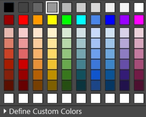 |
| Nickel Plated Connector Contact or Pin or Component Lead that is Nickel or Silver Plated, etc. | Silver | 204, 204, 204 | #CCCCCC | 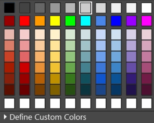 |
| Tin Plated Connector Contact or Pin or Component Lead that is Tin Plated, etc. | Tin | 217, 217, 217 | #D9D9D9 | 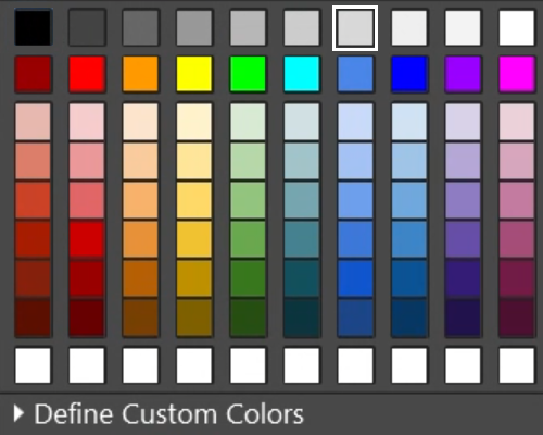 |
| Pin 1 Indicator Mark, Logo, Package Code, Text, White Resistor Stripe, etc. | White | 255, 255, 255 | #FFFFFF | 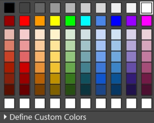 |
| Red Light Emitting Diode (LED) Lens Color, Red Component Body, Red Resistor Stripe, etc. | Red | 255, 0, 0 | #FF0000 | 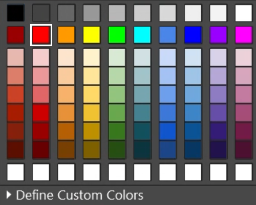 |
| Amber or Orange Light Emitting Diode (LED) Lens Color, Amber or Orange Component Body, Orange Resistor Stripe, etc. | Amber or Orange | 255, 153, 0 | #FF9900 |  |
| Yellow Light Emitting Diode (LED) Lens Color, Yellow Component Body, Yellow Resistor Stripe, etc. | Yellow | 255, 255, 0 | #FFFF00 |  |
| Green Light Emitting Diode (LED) Lens Color, Green Component Body, Green Resistor Stripe, etc. | Green | 0, 255, 0 | #00FF00 |  |
| Blue Light Emitting Diode (LED) Lens Color, Blue Component Body, Blue Resistor Stripe, etc. | Blue | 74, 134, 232 | #4A86E8 |  |
| Purple or Violet Light Emitting Diode (LED) Lens Color, Purple or Violet Component Body, Violet Resistor Stripe, etc. | Purple or Violet | 153, 0, 255 | #9900FF | 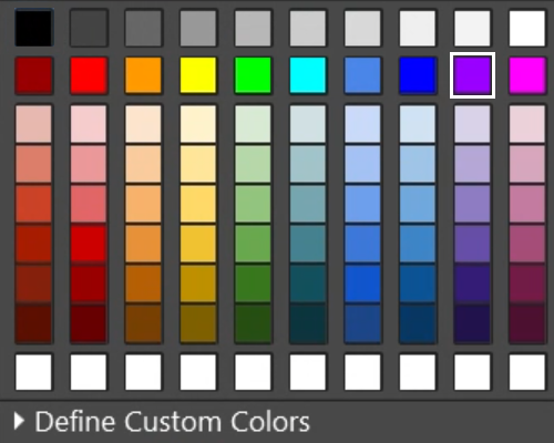 |
| Gold Plated Connector Contact or Pin or Component Lead that is Gold Plated, General Gold Plating, etc. | Gold | 230, 145, 56 | #E69138 |  |
| Ceramic CAP Coating, Brown Component Body, Brown Resistor Stripe, etc. | Brown | 120, 63, 4 | #783F04 | 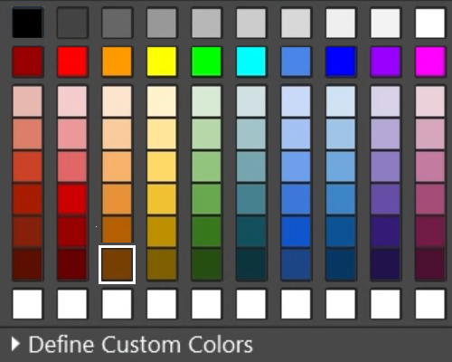 |
| Beige or Natural Connector Body, Tantalum CAP Molded Plastic Body | Beige | 255, 242, 204 | #FFF2CC |  |
Dimensions
3D models should be created using the following dimensions:
-
Nominal dimensions for length and width.
-
Maximum dimension for package height.
-
The standoff height should be its minimum value. (If not in the datasheet or zero in the datasheet, then use 0.05 mm as the standoff height).
Logos
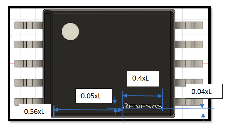
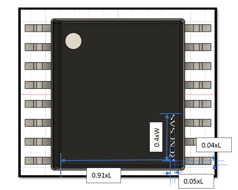
When creating logos in 3D models, the package can have a larger width or length (the priority is width if both are the same). In this case, the placement of the logo is explained below. In the examples below, L = the component body length.
If width > length:
-
Place the logo on the package with a horizontal distance of 0.52xL to 0.6xL from the left edge and 0.035xL to 0.045xL from the bottom edge. Ensure the logo's aspect ratio remains unchanged, and its length does not exceed 0.4xL.
-
Extrude the logo into the package surface by 0.01 mm and color it white with HEX (#FFFFFF) or RGB (255, 255, 255).
If width < length:
-
Place the logo on the package with a vertical distance of 0.87xL to 0.95xL from the left edge and 0.035xL to 0.045xL from the bottom edge. Ensure the logo's aspect ratio remains unchanged, and its length does not exceed 0.4xW.
-
Extrude the logo into the package surface by 0.01 mm and color it white with HEX (#FFFFFF) or RGB (255, 255, 255).
Package Codes
When creating package codes in 3D models:
-
Place the package code with a distance of 0.035xL-0.045xL from the left edge and 0.035xL-0.045xL distance from the bottom edge horizontally. The package code length should not exceed 0.4xL. The package code width should not exceed 0.05xL.
-
Extrude the package name inside the body by 0.01 mm and color it white with HEX (#FFFFFF) or RGB (255, 255, 255).

Pin 1 Identification Mark
When adding the pin 1 identification mark to a 3D model:
-
Place it on the top surface at the corner where Pin 1 will be located, place a square of side length 0.15xL, then place a circle at the diagonally opposite corner of the square of diameter 0.15xL.
-
Extrude the circle inside the body by a distance of 0.1 mm.
Exception
In case of a collision with any other mechanical section/geometry, during the creation of a 3D model, shift the logo and package by a minimum of 1 mm until the logo and code are both cleared from that geometry.
Leads Trimming
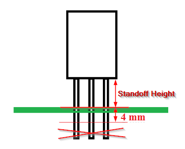
The leads of all through-hole packages (except connectors) should be trimmed. Lead length after trimming should be equal to Standoff Height + 4 mm.