Previous article
What Will Quantum Computer Components Look Like?
Octopart Staff
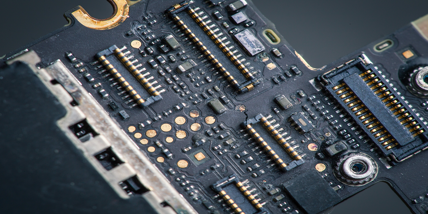
Anyone who’s ever looked inside an old desktop computer and unplugged a ribbon cable is familiar with the humble pin header. This connector is a simple but effective way to connect two boards together in a stacked arrangement. In fact, it’s so popular that it’s been used to build add-on shield boards for popular platforms like Arduino and Raspberry Pi, both of which have seen success outside the maker space. In a recent engagement with a client, I was surprised to see how they had stacked up multiple Raspberry Pi boards to run some critical equipment, which shows the importance of board-to-board connectors in these types of modular systems.
Even though pin headers are simple, it doesn’t mean they aren’t useful. However, they aren’t the only option, and there are many board-to-board connector options for high speed/high frequency systems, or for high voltage/high power systems. These connectors find their way into systems as diverse as military equipment to medical equipment. If you’re taking a modular design approach to your next hardware platform and you need to link multiple boards together easily, consider board-to-board connectors instead of cables. There are many cost-effective options on the market that can ensure signal integrity and rugged design in a range of systems.
Board-to-board connectors come in a variety of shapes and sizes to give a modular feel to a multi-board PCB system. There are many types of common board connectors, and different vendors have their own product lines that fall generally into one of the categories listed below:
Pin headers: Most designers are familiar with the 1-row or 2-row pin header arrangement with 1 mm pitch. There are variations on this style, including stacked pin headers. Pin headers can be shrouded and keyed (even multi-keyed) to guarantee pinouts match when boards are connected.
Mezzanine connectors: This type of board-to-board connector joins two parallel printed circuit boards in a stacked configuration. There are many mezzanine connector styles. Note that a pin header can be used as a mezzanine connector.
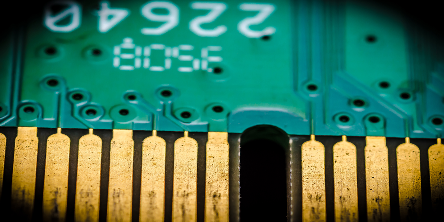
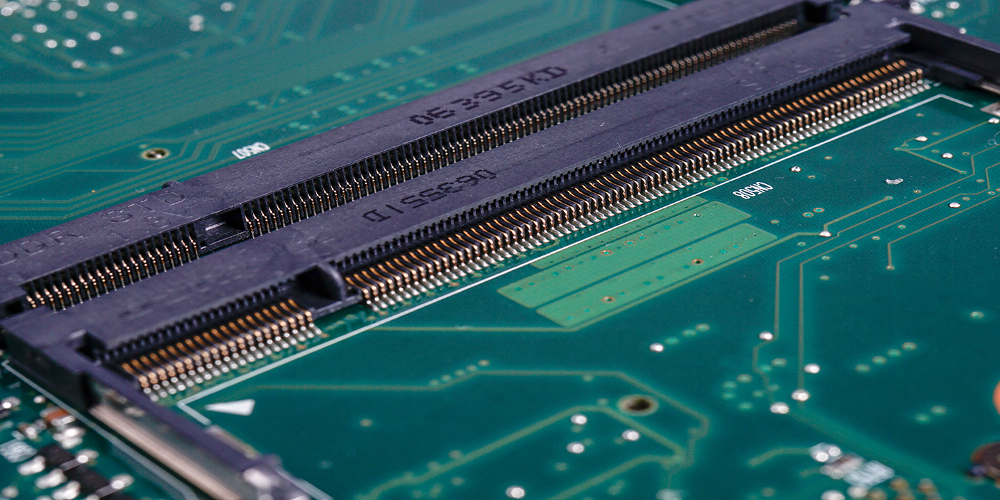
Edge card connectors: This style connector is most commonly known for its use in RAM sticks and COMs/SoMs. Really, it can be used for any board-to-board connection along a board edge, whether with a custom or standardized pinout.
Backplane connectors: This type of connector deserves its own category, both due to its need to accommodate high data rates and very rugged construction.
Standardized connectors: Some connectors may be developed to meet very specific industry standards beyond edge connector styles for add-in cards. Standards organizations that have defined specific connector styles include VITA (for backplanes), PCI-SIG (PCIe cards), IEEE (e.g., 1386 standard for mezzanine), JTAG, PC/104 (square-post pin headers), and others.
There are many other connectors that don’t fall into one of the above categories. The image below shows an example of some typical products that fall within these categories.
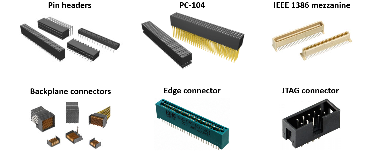
The image above is just a subset of all the different board-to-board connectors available on the market. Obviously, there are many variations on these connectors with different pin/pad counts, key/shroud styles, mounting styles (SMD vs. through-hole), and specifications. When you’re looking through a vendor’s website or filtering through a parts search engine, there are a few different ways vendors will categorize their parts.
Within these different types of board-to-board connectors, they may be classified as ruggedized, high speed, high frequency, high current/high power, or some other designation. This is largely marketing speak as there is no universal definition of a high speed connector, high power connector, etc. One important exception is backplane connectors, which are strictly defined in the ANSI/VITA standards, where specific styles pair with different media (copper, fiber, or coaxial cable). Another highly standardized connector style is the IEEE 1386 mezzanine connector.
As is the case with many other components, vendors will target specific industries with their products and will try to target specific applications in those industries. As a result, you’ll see styles of board-to-board connectors that might be highly ruggedized with hard plastic shielding as they target areas like automotive, aerospace, industrial systems, or power products. In general, you can usually find a ruggedized version of a standard connector that has the same pinout, mounting style, and pitch as its less rugged variant.
Now we can look at some of the points to consider when selecting board-to-board connectors. First, let’s look at some specifications, then we can think about the advantages of different connector styles.
Board-to-board connectors have some electrical specifications that should be considered beyond just the connector style:
Pitch and pin count: Unless you’re designing to a specific application, or you need high speed/high frequency or high current, you’ll probably start by looking at the pitch/pin count required in the connector. With low power and low speed signaling, just about every connector can handle your power requirements while ensuring signal integrity.
Power handling: This is normally quoted as current at a specific voltage per pin. Most connectors can handle a few Amps at typical application voltages. Make sure to check the voltage as it is common to supply both power and data through a cable; you’ll want to make sure your power does not exceed the voltage rating.
Governing standard: Any industry standards on connectors can govern form factor (some examples are discussed above), or they can cover testing and application specifications. Make sure to check these to ensure your connector style will be compliant.
Environmental ratings: Specifications include power variations with humidity cycling, exposure to gases, and testing at high temperature. This gives you a good idea of where the connector can be used to ensure reliability.
Data rate/frequency limit: For high speed data channels, you’ll see a recommended data rate limit, which the vendor will determine through extensive testing. Data rate limits are just a recommendation, and you might be able to get past these in your system. Be sure to test your system thoroughly if you plan to violate a data rate/frequency specification.
Mechanical specifications: High-quality board-to-board connector datasheets may include some data on mechanical shock, vibration, pulling force, or other specs that help a designer understand ruggedness. Note that these may be listed as test results meant to comply with some industry standard.
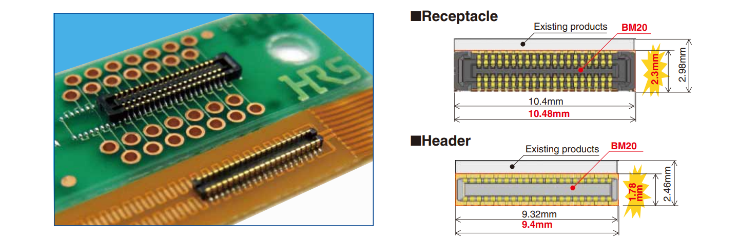
Form factor: Some board-to-board connectors (like edge connectors) can be rather bulky. Other connectors are specifically designed to have a low profile, such as the BM20 series of low-profile mezzanine connectors from Hirose. Watch out for the form factor and enclosure requirements in your system.
The various styles shown in the previous section might be a constraining factor as you might need to interface with an existing system, so you won’t have freedom to choose any connector. In many cases, the consideration starts with some electrical or mechanical constraint, followed by choosing the form factor or connector style you need to hit your profile/enclosure requirements.
If you do have freedom to choose your connector style and form factor, there are some advantages to each type of connector that should be considered.
With so many styles of board-to-board connectors on the market, it’s impossible to provide a complete comparison between every type of connector. However, there are some basic points to understand about different connector styles that reveal their advantages or disadvantages in different systems.
Edge connectors use sliding contacts to make an electrical connection, and these can eventually wear away after making repeated connections. Wear can happen on the card side or the receptacle side. If the board will need to be repeatedly connected and removed, alternative styles may be a better choice as many of these will have a longer contact lifetime.
Some connectors have a coaxial style that enables high power transfer, provides shielding, and advantages for RF systems (see below). Fully shrouded connectors are ideal for higher power applications and will have much higher current ratings without being excessively large on the board. This is a better option than a pin header, which may have as low as 1 A current rating and no useful high-speed/RF data.
Your connector orientation may allow for parallel boards, but the board might be able to be removed horizontally rather than vertically. For example, the Hirose connector shown above requires vertical removal, but there are edge connectors and mezzanine connectors that horizontal insertion/removal while maintaining a very low profile. This can be invaluable in low-profile applications where an add-in card needs to be accessed.
If you’re not worried about high current, high isolation, or highly precise signal integrity, stackable pin headers are a great way to add multiple levels of modularity to your system. Pin header blocks can be selected so that they are stackable, which allows multiple cards to be placed on a bus or allows power to be provided to multiple boards in parallel. If you need data access at every module, make sure the pinouts match throughout the pin header stack.
At high speeds/high frequencies reaching to Gbps/GHz levels, signal integrity becomes an important point to consider when selecting board-to-board connectors. Look for some of the following metrics in datasheets or from your manufacturer’s support pages:
Impedance: RF connectors with coaxial topology will have a specified impedance as they will need to interface with a specific system impedance. The impedance specification is valid up to the stated bandwidth, which might be a -3 dB frequency.
S-parameter data: If you want to do any kind of simulation with your connectors, then you’ll need S-parameter data. This is quite important with technologies like PAM4, SerDes channels, or newer high speed signaling standards (PCIe, GDDR6, etc.) as these simulations are an important part of system validation.
Pin-to-pin isolation: RF board-to-board connectors may have all pins entirely shielded, which is not always the case for other connector styles. These connectors will have high isolation and low pin count. They also tend to be bulkier. Some of these board-to-board connectors will have available cable connector variants.
When you need to filter through multiple vendors and find specific types of board-to-board connectors, use the advanced search and filtration features in Octopart. The electronics search engine features in Octopart can help you choose connectors by industry, technical specifications, signaling standard, and many other filters to suit your needs. You can also access distributor pricing data, parts inventory, parts specifications, and CAD data, and it’s all freely accessible in a user-friendly interface. Take a look at our connectors page to find the components you need.
Stay up-to-date with our latest articles by signing up for our newsletter.