Previous article
One Year Later: How the Electronics Supply Chain Has Adapted to COVID
Octopart Staff
These days, transistors come in all shapes and sizes, whether they are integrated into a CPU or available as discrete components. Any transistor requires some current to switch between ON and OFF states, thereby allowing current to flow across the device. Larger transistors, both physically larger and in terms of their current output, require more power for switching. This power can be provided by a gate driver IC, which is specialized for providing a buffer between a controller and a power transistor.
Not all applications will need a gate driver IC. High frequency applications may include an optimized gate driver circuit inside a transceiver or other RF component to provide the required power for switching a transistor amplifier, including in RF power amplifiers. These components are an integral part of power systems as they provide the required switching power while also protecting other critical components. Here’s how these components work and how to go about choosing a gate driver IC.
As was mentioned above, a gate driver IC provides high current to a high-power transistor, such as an IGBT or a MOSFET, in order to fully drive it into the conduction state. These components receive a low-power input from another component, such as an MCU or other controller IC. In this way, the gate driver IC acts like a buffer between the MCU and transistor. The typical arrangement for a gate driver IC in a signal chain is shown below.
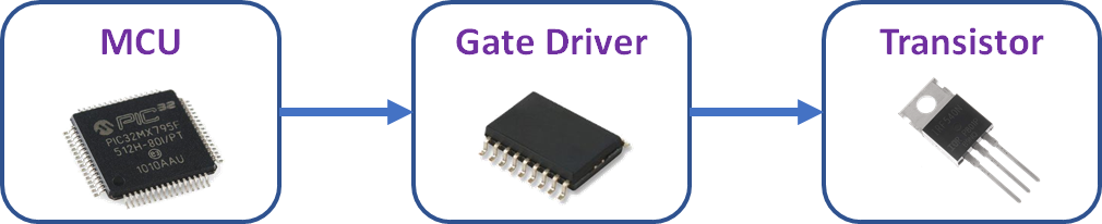
Signal chain for a gate driver IC
Although the basic purpose of a gate driver is to act as an amplifier for driving a large transistor, there is a deeper reason a gate driver IC is used for switching. The primary goals in using a specialized gate driver IC are:
Reduce switching losses in the load transistor
Decrease the load transistor’s switching time
Drive the transistor completely into the conductive/non-conductive state
A third goal, which is not provided by all gate drivers, is to provide isolation between the load and the controller. This is provided by a small internal transformer in the gate driver; such components are called isolated gate drivers.
All transistors have some nonlinear capacitance, i.e., they act like varactors. When the load transistor is switched, some charge remains on the gate region that keeps the channel in its current non-conducting or conducting state. Once another current pulse is applied, high heat can be generated in the transistor if the switching signal is slow or runs at low current. Applying the switching signal at higher current provides faster switching between states with less loss.
The arrangement shown above and the need for complete, fast modulation of high power transistors makes a gate driver IC important in any application where a high-power load requires complete switching and modulation. If we were to do this with an MCU, the large current draw from the MCU could cause it to overheat and fail, thus the need for a gate driver. Three typical applications are in switching DC-DC converters, power inverters, and motor driver circuits.
Once the gate driver receives an input from the controller, it outputs high current to a single transistor, or multiple transistors in parallel. Note that a parallel arrangement of transistors is common, particularly with IGBTs or MOSFETs, in switching DC-DC converters with high current output. This type of system is necessary when an array of large transistors requires several amps of current to fully switch into the conduction state, which is typical in high power converters.
In terms of placement in a signal chain, the gate driver will sit within a feedback loop, as shown in the image below. An MCU can be used to implement a simple control algorithm to provide stable voltage output, or it can be used to change the output voltage in response to user input. In the case where a high current regulation is desired from the converter, a current sense amplifier might be used in the feedback loop before the MCU/PWM driver as this gives an accurate current measurement for use in a control algorithm.
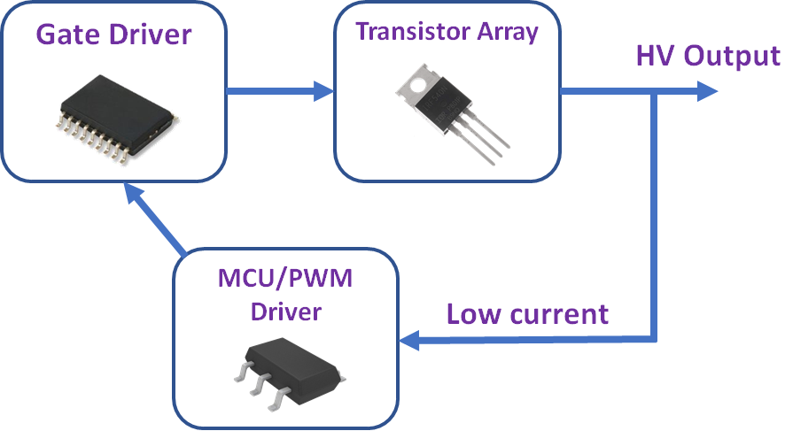
A gate driver IC in a feedback loop for DC-DC conversion.
This is related to DC-DC conversion, although we are now switching continuously to produce an oscillating waveform. Isolated gate drivers are needed in this application to isolate the DC source and controller from the output side. Inverting logic is used on the load side, while the gate driver is supplied with a low-current oscillator waveform.
This principle application involves a transistor driven with a PWM signal. In this case, the gate driver receives a PWM signal and outputs an amplified, high current version of the PWM signal. This is then sent to a transistor array to drive a motor. Examples include driving stepper motors and brushed motors. Isolated gate drivers are normally used in this application as they appear between the MCU/controller and the motor on the output side.
Output current is the most important specification you’ll need to look at, and this specification should be compared to your transistors specifications. Here are some other important specifications you should examine when selecting a gate driver IC:
Type of gate driver. There are four types of gae drivers:
High-side: These are used to drive power transistors that are connected to a positive supply rail with no ground reference connection.
Low-side: These used to drive transistors that are connected to a negative supply rail with no reference connection.
Half-bridge: These components contain low-side and high-side driver circuits, making them more flexible.
Three-phase: These gate drivers are used in three-phase systems.
Rise and fall time. This is important for reducing switching losses. In particular, switching with faster rise/fall times will ensure lower switching losses in the transistor.
Max. frequency. This is important in all three of the above applications.
Temperature rating. As these components are operating at high power, they may need a heat sink for cooling.
The FAN73912MX gate driver IC from ON Semiconductor is one example of a high power component that can be connected in half bridge configuration. The application circuit shown below illustrates how a high power gate driver can be integrated with a controller in a high voltage system.
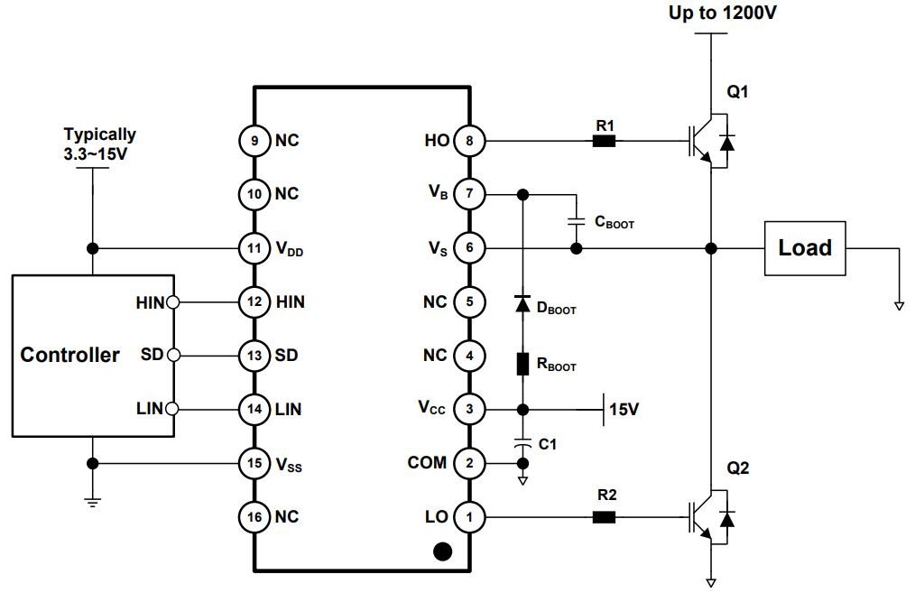
FAN73912MX gate driver IC application circuit. From the FAN73912MX datasheet.
When you’re looking for power electronics components, including transistors and gate driver IC options, try using the advanced search and filtration features in Octopart. You’ll have access to an extensive search engine with distributor data and parts specifications, all of which is accessible in a user-friendly interface. Take a look at our power management integrated circuits page to find the components you need for power conversion, conditioning, and management.
Stay up-to-date with our latest articles by signing up for our newsletter.