Previous article
Selecting a Power Factor Correction IC for AC-DC Conversion
Octopart Staff
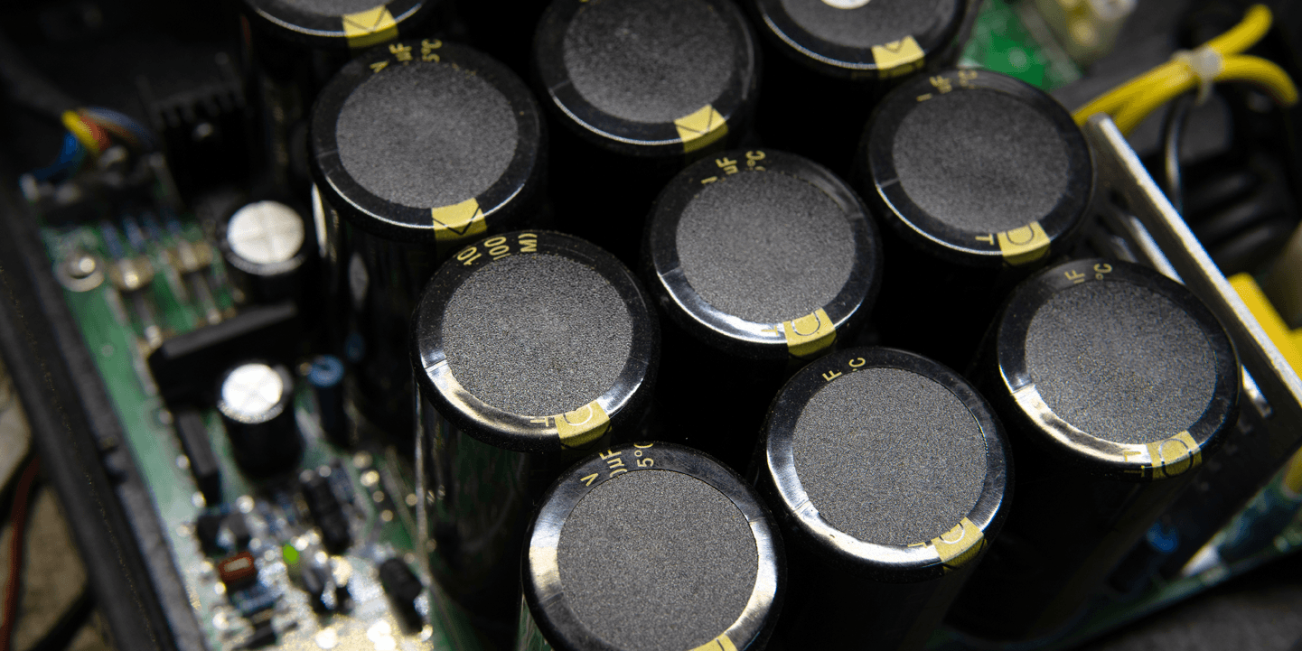
Any regulated power supply needs to be designed to have low noise at the input and output to the regulator section. Getting noise low relies on selecting the right filter capacitor for your supply. Depending on the current, these capacitors can be quite large, or you may need to place a large number of capacitors in parallel. With the right capacitor (or capacitor bank), you’ll be able to dampen voltage ripple from your rectifier while ensuring a long lifetime.
Although most subjects involving “filter capacitors” simply refer to the output capacitor on a rectifier, it can also refer to the capacitor on the output of a voltage regulator. A filter capacitor could also refer to components used in an EMI filter on the input to a power supply. Fortunately, some of the same principles apply when selecting the best capacitors for power supply filtering. Take a look at our guide to see how to select the power supply capacitor you need.
As much as we would like to just go onto DigiKey and bring up a page for filtering capacitors, this route doesn’t exist. The truth is, different capacitors are useful for different purposes, and the specifications in various capacitors determine its appropriate application. Obviously, you’ll need to size the capacitor to the appropriate value to provide ripple suppression (larger is better), but it goes beyond simply calculating capacitance.
To start selecting the best capacitors for power supply filtering, you need to get into a capacitor datasheet and delve through some specifications. Some of the important specifications are as follows:
Capacitor material: Your capacitor might be a ceramic, electrolytic, tantalum, polyester, or other material. This determines the useful capacitance range, as will as other specifications like the voltage rating and parasitics.
Working voltage rating: This basically tells you the maximum DC or AC RMS voltage that can be applied to the capacitor. The specified working voltage is valid within a certain operating temperature range, which may be displayed on a graph.
Parasitics or self-resonant frequency: These specifications are stated in different ways, depending on the manufacturer. The manufacturer might only state the ESR and ESL values, or the ESL and Q-factor values, which can be used to calculate the self-resonant frequency and bandwidth. Alternatively, the impedance spectrum will be shown in a graph, which can then be used to calculate the ESR and ESL values.
Temperature coefficient: Most designers don’t worry about this, but it becomes important as the capacitance of a real capacitor will change with temperature. Therefore, you should choose a capacitor with the smallest temperature coefficient if your product will operate over a broad temperature range.
Polarization: Filter capacitors for DC circuits have some specified polarization, which states the direction the electric field should point across the capacitor. Excessively large AC voltage across a polarized capacitor can destroy the component prematurely.
This range of specifications will cover all the relevant filtering applications you’ll work with. The trick in selecting a rectifier output capacitor, EMI filter capacitor, or power regulator output capacitor is to balance the required capacitance value with the other important specifications. The block diagram shows some spots where you will need to select different types of capacitors for your design.
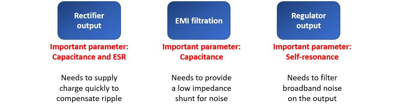
The three typical spots to put a filtering capacitor and the important parameter in each case are shown above.
Here, the important point to consider is the capacitance value and the ESR value. These values are important for two reasons. First, the capacitor needs to be sized such that the ripple voltage is minimized during a half-period of the line oscillation. To size the capacitor you need, simply use the formula shown below:

Capacitor value required to keep peak-to-peak ripple at a specific value.
Here, the current term refers to the current that needs to be supplied by the capacitor when the rectifier current and voltage drop during rectification. For a given current, simply select the desired voltage ripple (as a magnitude change) to calculate the required capacitor value. Theoretically, an infinite capacitance will produce zero ripple.
The ESR value is a parasitic that determines how fast the conductors in the capacitor will heat as the component charges and discharges. ESR also defines the smallest amount of time over which the capacitor can discharge. For a system connected to grid power, you’ll be working at 50 or 60 Hz, so you won’t need to worry about the discharge time. The filter capacitor should be chosen with low ESR value while also providing high capacitance; ceramics are a good choice here as they tend to have very low ESR.
When designing an EMI filter, the important point is the topology of the circuit and the exact capacitance value. Self-resonance is also important here because, if the system operates beyond a capacitor’s self-resonance frequency, a capacitor will “act” like it has a different value. In addition, other reactive components (e.g., inductors, chokes, or ferrites) will interact with the capacitor to create complicated coupled oscillations. Be sure to validate your design with simulations to determine the right capacitance needed for filtering.
The main goal in EMI filtering on a power supply line is common-mode and differential-mode noise cancelation. I always use unpolarized capacitors for EMI filters that are connected to AC lines and I recommend other designers do the same. As long as the self-resonance frequencies of all capacitors are sufficiently large for the noise bandwidth you care about, then you do not need to worry so much.
When placed on the output of a regulator (e.g., switching regulator or LDO), the capacitor plays a dual role. First, its role is to charge and discharge during switching so as to keep the DC output stable. Second, its role is to shunt high frequency conducted EMI back to ground. Polarized or unpolarized capacitors can be used for this application as long as the self-resonance frequency is sufficiently high.
For the case of a switching regulator, the PWM signal in the regulator will generate harmonics that stretch out to 100’s of MHz, which will then appear as radiated EMI and conducted EMI on the output. This EMI can be reduced by adding a small amount of damping in the circuit, such as with a ferrite on the output of the switching MOSFET in the regulator. The challenge here is to use a capacitor with a sufficiently high self-resonance frequency, possibly with higher ESR if current is low enough. If the output current is large, then go for a ferrite or inductor to induce more damping into the self-resonance.
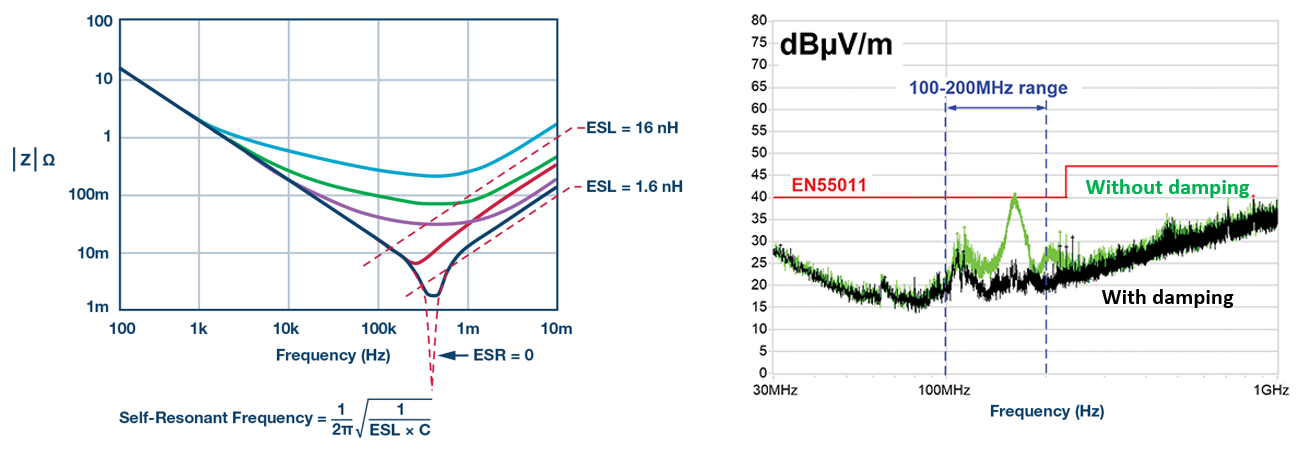
How damping affects self resonance. On the left, increasing damping into the system increases the capacitor’s impedance at resonance. The effects on radiated EMI in a switching converter (output capacitor self-resonance = 146 MHz) are shown on the right.
Another important use of capacitors outside of power supply design is for impedance matching networks in high frequency/high-speed circuits. However, using a reactive component like a capacitor for impedance matching is more common for antennas rather than high-speed driver/receiver pairs. This aspect of capacitor use is a bit more specialized, and I’ll likely address this in a future article.
When you’re looking for the best capacitors for power supply filtering, try using the advanced search and filtration features in Octopart. When you use Octopart’s search engine, you’ll have a complete solution for electronics sourcing and supply chain management. Take a look at our passives page find the capacitors you need.
Stay up-to-date with our latest articles by signing up for our newsletter.