Previous article
How Embedded AI is Evolving in 2020 and Beyond
Octopart Staff
Ever wonder why your phone takes hours to charge with an older wall charger, but it charges very quickly when connected to a newer wall charger? If you’re an electronics designer, you know the problem: the older wall charger isn’t delivering enough power to charge your battery in a reasonable amount of time because its output current is too low. Newer phones are power-hungry beasts and need more current to charge to full capacity quickly.
USB has been around since 1996, but the newer USB-PD over Type C connectors allows for higher power transfer to a mobile device, allowing for faster charging. USB-PD even allows bi-directional power exchange, so your phone could (in theory) power your laptop. Here are some of the components you’ll need for a USB-PD system and how to design your next product to support USB-PD.
The central premise of USB-PD is simple: transfer more current at higher voltage into a connected device, thereby charging the battery faster. The USB-PD standard (under the current Rev. 3.0) allows up to 100 W to be delivered between devices at up to 20 V/5 A over USB Type C connectors. That is, however, provided the receiving device can withstand that much voltage/current. Those numbers in the guidelines were intended for charging laptops, tablets, and other devices that used to require a barrel connector to receive sufficient power. Just for perspective, my 1-year old laptop requires a 19.5 V/3.3 A DC power supply for charging, which is within the purview of the USB-PD protocol.
USB-PD transfers power over a USB Type-C cable and is intended to be vendor agnostic. In other words, the USB-PD standard was intended to provide a way for product designers to develop a universal charging solution that is adaptable to a variety of products. Being vendor agnostic hasn’t stopped Qualcomm and Samsung from developing some proprietary charging techniques (Quick Charge and Adaptive Fast Charging, respectively) for their mobile phones. However, USB-PD can still be used with these and other mobile devices, or your new IoT/mobile device.
The table below shows the standardized voltage levels used for sourcing at different power levels. The components you choose should satisfy these specific output voltages and current ranges in order to be compliant with the USB-PD standard.
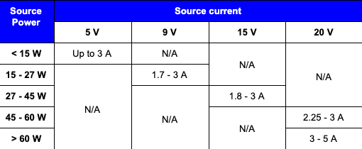
Note that the USB-PD standard is only a suggestion, not a requirement. For example, the recent Apple iPhone charges at 14.5 V/2 A (29 W), making it compatible with the 15 V section of the above table.
Because different products require different voltages and currents, a charging host needs to negotiate with connected devices and determine the right voltage/current to supply. Components need to provide the following functions:
Some systems will need multiple USB-PD power switches and/or a multiplexer to provide power output to multiple downstream devices. Other power system components will be needed, such as for input/output power regulation and overcurrent suppression. The last point is important in that it enables the bi-directional nature of USB-PD (dual-role mode); this is where a dedicated USB-PD controller is used to negotiate power transfer between devices. Here are some examples of essential components for any USB-PD charging system.
The FUSB302BMPX from ON Semiconductor is a power switch that outputs up to the full 100 W under the USB-PD specification. This component was released under Rev. 2.0, but it is still compatible with newer Rev 3.0 devices and is still in active production. This component enjoys applications in USB-PD for laptops, phones, portable battery-powered charging units, and cameras.
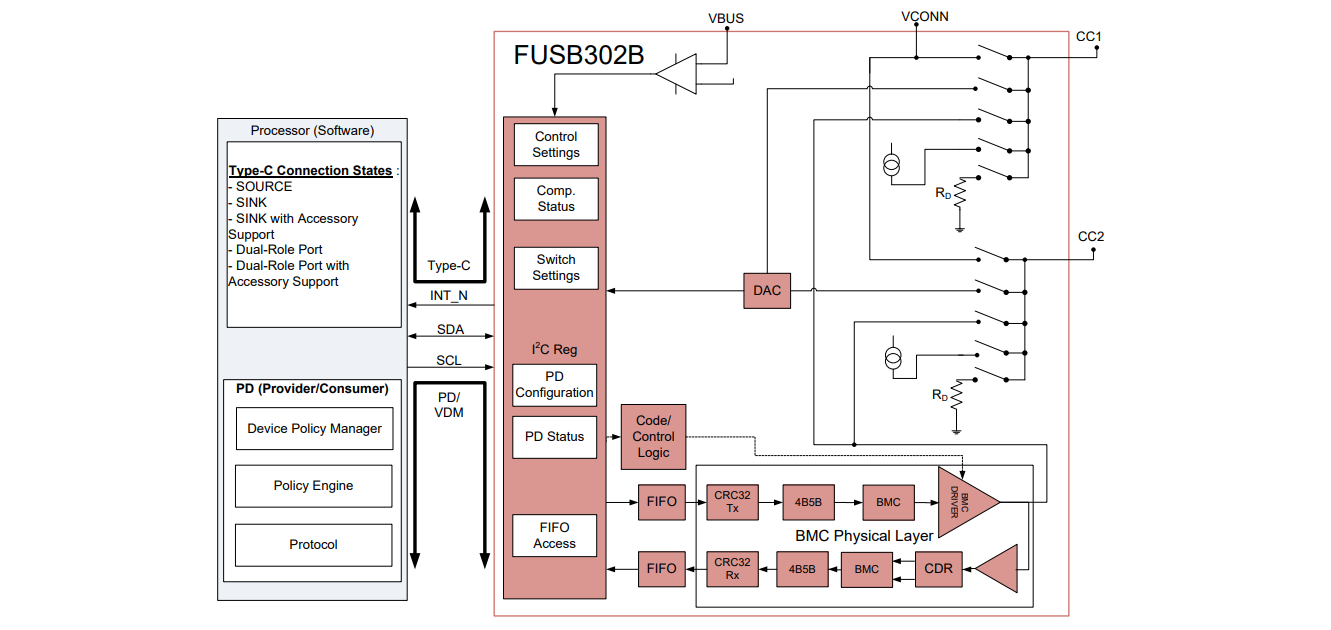 USB-PD power controller block diagram, from the FUSB302BMPX datasheet.
The PTN5100DBSMP from NXP Semiconductors is a USB-PD compatible PHY interface for a single Type-C USB port. This IC includes an LDO to support a dead battery condition in a downstream device. This IC can also be configured as the input PHY layer for a receiving device, or it can be put into dual-role. Configuration is performed over an SPI interface, and status updates are provided over I2C. This IC also provides gate control signals for PMOS power MOSFETs on the power bus for downstream power delivery.
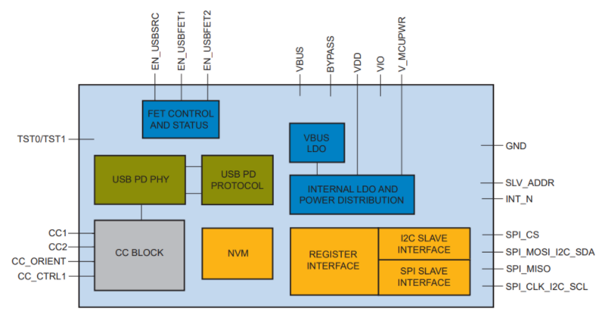 Functional block diagram from the PTN5100DBSMP datasheet.
(Alt text: USB-PD block diagram from the TPS65982 datasheet)
https://drive.google.com/open?id=1mNBypQutN1Y7_tr6eVTaTVmfc0ygDNw3
Functional block diagram from the PTN5100DBSMP datasheet.
(Alt text: USB-PD block diagram from the TPS65982 datasheet)
https://drive.google.com/open?id=1mNBypQutN1Y7_tr6eVTaTVmfc0ygDNw3
The TPS65982 from Texas Instruments is a USB-PD power switch, controller, and multiplexer all in a single unit. Other components separate important functions into different ICs, giving this component a big advantage in products with USB-PD. This device includes a USB PHY layer, 3.3 V LDO output for dead battery support, and 5 V/ 3 A Switch to VBUS for Type-C power. It can output up to 20 V/3 A, making it compatible with modern mobile devices. Texas Instruments is arguably the current leader in these components, with the only drawback being the limited 60 W power output.
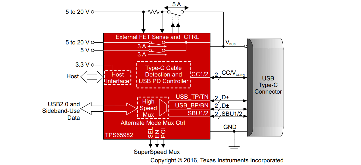 Functional block diagram from the TPS65982 datasheet.
Your next mobile, IoT, or other power system can charge much faster when you design your power system to the USB-PD standard. The above components can help get you started with your next power system, and you can find the components you need with when you use an electronic parts search engine like Octopart. The advanced filtering help you narrow down to the right components for your next system.
Stay up-to-date with our latest articles by signing up for our newsletter.